Raspberry Pi-Zero ArduPilot
RZero

Index
DIY Raspberry Pi Zero Ardupilot “R-ZERO” 6
Introduction
Flight Control Board FCB is essentially a microcontroller board that reads input from sensors and
remote control and processes these inputs based on algorithms that determine the output signals
that rotate servos and motors to drive/fly the vehicle.

FCB board normally contains beside a microcontroller some of sensors mainly gyro, acc, mag
& barometer on the same board. While GPS normally comes as a separate part and connects
to a socket on the board.
So almost any board can be turned to FCB if we attach the right sensors and provide a way for
RC-in & RC-out. This is true. But from a Software perspective writing autopilot systems using
today's features is almost an impossible task for one person. And even if we have the talent.
we will never have the time spent in testing and validating features by all ardupilot users.
Fortunately, Ardupilot, the best open source autopilot already supports running on Linux.
Please check this here we find the following list:

The very nice thing about the above list is the existence of Raspberry Pi based boards such as NAVIO2.
That is what we are looking for because since ardupilot is open source then we will find many reusable
modules for RPI and a model to follow to define our board.

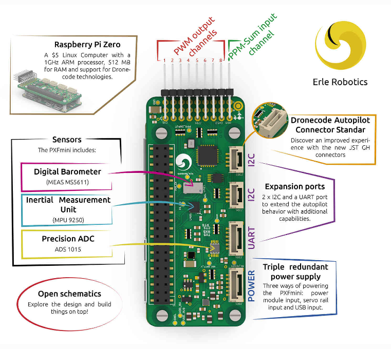
Even better we can find PXFmini board. It is a Raspberry PI Zero based board.
DIY Raspberry Pi Zero Ardupilot “R-ZERO”
From this point it seems we have a very good start. We will see how there are many reusable
Raspberry Pi codes. Most of them are very critical and not an easy task to write from scratch.
However as we mention above in our pseudo definition of FCB, FCB is processor & sensors
which is not the case for RPi-Zero. PXFmini consists of two boards, one of them is Raspberry Pi Zero
and the other is a board that holds sensors, RC-in & RC-out pins.
Now we only have Raspberry Pi Zero, and we need to make our second board.
Our second board should contains:
RC-in: to read signals from RX.
RC-out: to output signals to motors.
Sensors: to identify vehicle status and location.
Gyro
Acc
Compass
Barometer
GPS
Volt & Amp sensor for battery.
LEDS to display status.
Design Decisions
Let us first start with GPS as it is the easiest part. We only need to connect GPS TX/RX with
Raspberry Pi Zero TX/RX and it will work with no code changes. We only need to add a parameter
in the ardurover command to initialize the serial port. So no extra hardware is needed here.
For RC-In the good news is that Ardupilot already has a reusable code, a class called RCInput_RPI
for this part, you can even edit GPIO ports to use and even determine if you want to use 4 or 8 channels
or a number in between. This class is complex and advanced. I am glad I found it ready to use.
Again no extra hardware is needed here.
For LEDs again we can find a reusable code, a class called GPIO_RPI that is ready to use.
Although there is no extra hardware interface but we had to add LEDs each LED is connected in
series with a 10K resistor to limit the current and avoid burning out GPIO bin.
Now let's discuss harder parts. I used GY-80 with the following sensors:
L3G4200D (3Axis Gyroscope 2.4-3.6V)
ADXL345 (3 Axis Accelerometer. 2v- 3.6v)
HMC5883L (3-Axis Magnetic compass 2.16v-3.6v)
BMP085 (Pressure Sensor. 1.62v- 3.6v)
Again we are lucky as all these drivers already exist in Ardupilot code. Unfortunately Gyro & Acc
composite driver has some issues in implementation in the original Ardupilot repository.
So I had to rewrite it in a new way that is compatible with the way Ardupilot handles drivers
and their definitions. Technical details of these changes can be found here.
The reason I believe why this driver was somewhat buggy is due to it not used at all in the code so
it seems to be obsolete. However I found later an upgrade for this driver in another forked repository
but I believe my update is more compatible with the latest code style they use to call drivers.
This part was the first part I work on in this project, so I spent some time figuring out how to define a
board and attach sensors to it. Also what a correct driver software layout is. The problem I faced here
was that I use a composite sensor with I2C connection. PXFmini uses SPI connection and another
MPU sensor which is by the way available to buy but it was not available in the store at that time.
RC-out: This should not be the hardest part. Actually it should be a trivial part. Raspberry Pi boards
uses a 16-channel-pwm-servo-driver called PCA9685 this part has a defined driver in Ardupilot code
in a class named RCOutput_PCA9685. The last piece of this driver was sold moments before I asked
for it. And I failed to find it in electronic shops where I live. So I decided to build my own RC-output.
The system I have built is actually heavily based on multiwii code.
Multiwii is a very famous quadcopter firmware that can run other vehicles. It has been left with no
updates since 2016. CrazyFlight and similar firmwares are descended from Multiwii but support
STM32FX based flight controllers.
I2C ServoDriver
Well, this is considered an independent project that can be used in many other projects.
However, I had to build it as part of R-Zero project.
As I mentioned Multiwii is a very famous flight control firmware. However its feature is
not our concern here. What we really care about is its code for controlling actuators such as
servo and motors. And its built in configurations for many vehicles.
Besides it is a relatively very easy code to explore compared to Ardupilot.
I used to play with Multiwii many years ago, I have even transferred it to ArduinoDUE.
Anyway this was in the past, now we need to think of this code as a motor driver,
that we can send to it commands via I2C and it translates it to meaningful signals for
motors and servos. So I started by removing all unnecessary code from Multiwii.
And I added I2C slave code that receives code from Raspberry Pi via I2C.
Received values are directly injected into motors and servos with no mixing.
A safety feature was added to send MINCOMMAND value to motors if no signal is received
from I2C with a defined timeout.
I also had to write a driver basically cloned from RCOutput_PCA9685
called RCOutput_MW_I2C. It uses simpler commands but basically the same approach.
Using config.h we can define our vehicle actuators. I had to add MW_I2C_Rover as rovers
were not defined in this code. But many other vehicles are defined. However I must highlight that
I tested only on rover. So please check it carefully before you connect motors and propellers.
You can use simple small blue servos for testing, and you might need to remap output channels
in a function called mixTable().
Code for this project can be found here.
Problems
I found some problems with I2CServoDriver maybe because of conflicts between i2c slave
and timers used to generate pwm. Servos glitches with no good reason.
Anyway I could finally get PC9685 board and I activated RCOutput_PCA9685 and it worked
like a charm.
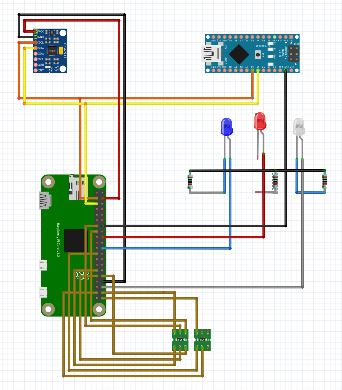
Technical Specification:
MPU GY-80 communication using I2C protocol with I2C Device Addresses:
I2C Address 0x1E is the HMC5883L
I2C Address 0x53 is the ADXL345
I2C Address 0x69 is the L3G4200D
I2C Address 0x77 is the BMP085
GPS UBlox connected to TX/RX directly.
RC-In: using GPIO: GPIO 5, 6, 12, 22, 27, 20, 21, 26.
RC-out: using Arduino D11, D9, D3 & D10. where D9 is a motor output for Throttle. & D11 for Steering in the rover.
For PCA9685 channels 1 & 3 are used and GPIO27 is used for enable the chip (not used in my code).
How to Start
First we need to compile ardupilot RZero branch. Using command: $ make rzero-rover
Then we can find the binary in subfolder ardupilot/build/rzero/bin/ardurover

We need to copy this file to Raspberry Pi Zero in /home/pi you can copy it in many ways, one of them is to open SDCard on your laptop and manually copy the file. Another easier way is to copy it using scp command.
scp ./build/rzero/bin/ardurover pi@YourRPI_IP:.
That is it.
When I run ardurover I choose it not to start until I connect to it using MissionPlanner or QGroundControl -my favorite- so that I can monitor each and every step.
sudo ./ardurover -A tcp:MyLapIP:wait -C:/ttyAMA0
You can also use other options such as:
sudo ./ardurover -A udp:MyLapIP:bcast -C:/ttyAMA0
Notice: If you make your mobile Wifi Hotspot it will take IP 192.168.43.246 which so you can add this network to your RPI zero and make it connect to your QGC on your mobile phone.
You can choose to remove “wait” and ignore initializing GPS in your first tests.
AutoRun Service
Create a file at: /lib/systemd/system/ardurover.service
[Unit]
Description=My Sample Service
After=multi-user.target
[Service]
Type=forking
ExecStart=/home/pi/ardurover -A udp:192.168.1.100:10100:bcast -C udp:192.168.1.139:14550:bcast
Restart=on-failure
[Install]
WantedBy=multi-user.target
Important Notice:
In the above version I ran ardupilot on pure linux. But Ardupilot need RealTime OS so we need to update the Raspberry PI OS and add Real Time Features.
To do that you need to follow steps from this link. It is straightforward yet not easy.
IMPORTANT real-time OS is not mandatory if you only run ardupilot without running extra apps. At least for rovers.
The Fatal Bug
This was totally unexpected. I found a bug that crashes ardupilot on RPIZero randomly.
I was due to using RCInput_RPI class. I took me a while to figure it out but I could finally fix it in this
[AP_HAL_Linux: Fix RCInput_RPI Segmentation Fault #14842].
Conclusion
In this project I learnt how to define a board of in Ardupilot, adding and updating sensors. It also required decisions about design and wiring.
Useful Links
Building an autopilot from scratch using Raspberry Pi Zero: Mini Zee.
Code with PCA9685 enabled with segmentation fault fixed https://github.com/HefnySco/ardupilot/tree/ppr_RaspberryZ_PCA9685
Code with Arduino MW-I2C enabled with segmentation fault fixed
https://github.com/HefnySco/ardupilot/tree/ppr_RaspberryZ