HefnyCopter
HefnyCopter is a firmware specially designed for KK boards.
There are two types of this firmware.
HefnyCopter
This
version targets the green and blue KK boards from HobbyKing. The main feature
of this version is that it allows awitching your Quadcopter from X to PLUS mode
without the need to reorient the board. The main concept of this feature
explained in this topic “quadcopter-stabilization-control-system”.
The hex
& sourcecode is available here . Please
make sure that you read the manual well before flying as POTS functions are not
the same as the original firmware of KK boards.
HefnyCopter2
This is
a complete new version and goes in parallel with HefnyCopter, i.e. there are
still updates on HefnyCopter so they are two parallel tracks.
This
firmware targets KK2 board. The board has LCD, Accelerometers, and Gyro. As
well as a beter processor ATMega324. This means you have better capabilities
here to help you to build a better firmware.
HefnyCopter2
still has the feature of mode switching from X to Plus. But now you can connect
your board via XBEE to your PC and receive telemetry data, you can work better
on you stabilization algorithm and enhance your quadcopter stability.
HefnyCopter2
also has the feature of supporting two TX, that means you can fly it with a
friend and train him/her how to fly the quad.
How HefnyCopter2 Helps to Improve Stabilization
Because of the ability of sending data to PC using XBEE, I
was able to visualize the data and try different approaches to filter out the
noise.
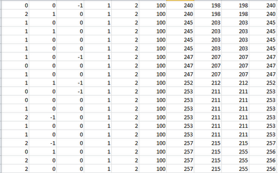
The Windows application that connects to XBEE has nice GUI interface for realtime display, however the more useful part is the CSV file that it dumps for the received data. In the below figure we can see the received data. Columns in order are:
Gyro_X, Gyro_Y, GyroX, Acc_X, Acc_Y, Acc_Z, M1, M2, M3, M4
 |
| Raw Data as received from XBEE in csv format |
Please note that Acc_X represent the pitch so it goes with Gyro_Y, also Gyro_Y increase when quadcopter rotates forward, while Acc_X increase while quadcopter rotates backward. i.e. Acc_X is related to Gyro_Y and with negative sign. Same applied for Acc_Y & Gyro_Y.
Acc_Z represents the gravity effects that is why it is not 0, it is 100 which is equivalent to 9.8 m/s, Gyro_Z is used to detect YAW so it has nothing to do with Acc_Z.
Values ranges from 500 to -500, while motor ranges from 0 to 1000. To keep logged data at reasonable size data is only transmitted when quadcopter is armed and motors are on. that is why the minimum values of motors Ms is 100 here in the sheet as below this values quadcopter ignores TX signal and send Zero to motors.
Let now study Gyro_Y values and apply some math on it.
 |
| Gyro_Y Data received from XBEE |
as we can see above this is Gyro_Y data, I added three more columns:
Move Avg
This is a moving average column, which means each value is added to the total and then divide the total over two.
Gyro_Y_Total = (Gyro_Y_Total + Gyro_Y ) /2
LPF
LPF stands for Low-Pass-Filter, here i used a complementary filter to reduce noise. Complementary filter is not a complex math at all, at least if we focus on the formula not the derivation, and try to understand it from the simple view point. The formula is as follows:
Gyro_Y_Total = (0.95 * Gyro_Y_Total) + (0.05 * Gyro_Y)
Each time we take small part of the signal and sum it to the total. assuming that the signal has high frequency noise, so we need to smooth it by taking part of the signal and accumulate it, to avoid taking peaks that represents high frequency.
Yes there are better ways to filter noise and at specific frequencies -as we can find in sound equalizer-, but computation is difficult and time consuming. If you are interested for more complex algorithms try Kalman Filter, or read topics about Fast Fourier Transform.
LPF2
This is the same as LPF. I only changed the factors, and took double the amount in LPF.
Gyro_Y_Total = (0.90 * Gyro_Y_Total) + (0.10 * Gyro_Y)
 |
| Gyro_Y under different filters |
You can see clearly from above how complementary filter does remove noise from signal. There are two lines red & blue in the complementary filter the one with some noise is LPF2 and the red smoother one is LPF where we take only 0.05 of the signal value.
HefnyCopter2 now implements complementary filters for Gyro_X, Gyro_Y & Gyro_Z and the result was a much smooth flying.
I am still working on studying different behaviors and values received from my quadcopter. I believe there is a much yet to be discovered -at least for me-.
Data Analysis Files can be downloaded from here.
Please follow up with us on HefnyCopter.net
No comments:
Post a Comment