Friday, August 21, 2020

Raspberry Pi-Zero ArduPilot PCA9685

Raspberry Pi-Zero ArduPilot

RZero


Index

Index 2

Introduction 3

DIY Raspberry Pi Zero Ardupilot  “R-ZERO” 6

Design Decisions 6

I2C ServoDriver 7

Technical Specification: 9

How to Start 10

Important Notice: 10

Conclusion 11

Useful Links 11


Introduction


Flight Control Board FCB is essentially a microcontroller board that reads input from sensors and

remote control  and processes these inputs based on algorithms that determine the output signals

that rotate servos and motors to drive/fly the vehicle.


FCB board normally contains beside a microcontroller some of sensors mainly gyro, acc, mag

& barometer on the same board. While GPS normally comes as a separate part and connects

to a socket on the board. 


So almost any board can be turned to FCB if we attach the right sensors and provide a way for

RC-in & RC-out. This is true. But from a Software perspective writing autopilot systems using

today's features is almost an impossible task for one person. And even if we have the talent. 

we will never have the time spent in testing and validating features by all ardupilot users.


Fortunately,  Ardupilot, the best open source autopilot already supports running on Linux.

Please check this here we find the following list:


The very nice thing about the above list is the existence of Raspberry Pi based boards such as NAVIO2. That is what we are looking for because since ardupilot is open source then we will find many reusable
modules for RPI and a model to follow to define our board. 


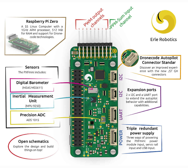
Even better we can find PXFmini board. It is a Raspberry PI Zero based board. 


DIY Raspberry Pi Zero Ardupilot  “R-ZERO”


From this point it seems we have a very good start. We will see how there are many reusable

Raspberry Pi codes. Most of them are very critical and not an easy task to write from scratch.

However as we mention above in our pseudo definition of FCB, FCB is processor & sensors

which is not the case for RPi-Zero. PXFmini consists of two boards, one of them is Raspberry Pi Zero

and the other is a board that holds sensors, RC-in & RC-out pins.


Now we only have Raspberry Pi Zero, and we need to make our second board. 


Our second board should contains:

  1. RC-in: to read signals from RX.

  2. RC-out: to output signals to motors.

  3. Sensors: to identify vehicle status and location.

    1. Gyro

    2. Acc

    3. Compass

    4. Barometer

    5. GPS

    6. Volt & Amp sensor for battery.

  4. LEDS to display status.


Design Decisions


Let us first start with GPS as it is the easiest part. We only need to connect GPS TX/RX with

Raspberry Pi Zero TX/RX and it will work with no code changes. We only need to add a parameter

in the ardurover command to initialize the serial port. So no extra hardware is needed here.


For RC-In the good news is that Ardupilot already has a reusable code, a class called RCInput_RPI

for this part, you can even edit GPIO ports to use and even determine if you want to use 4 or 8 channels

or a number in between. This class is complex and advanced. I am glad I found it ready to use.

Again no extra hardware is needed here.


For LEDs again we can find a reusable code, a class called GPIO_RPI that is ready to use.

Although there is no extra hardware interface but we had to add LEDs each LED is connected in

series with a 10K resistor to limit the current and avoid burning out GPIO bin.


Now let's discuss harder parts. I used GY-80 with the following sensors:

  1. L3G4200D (3Axis Gyroscope  2.4-3.6V)

  2. ADXL345 (3 Axis Accelerometer. 2v- 3.6v)

  3. HMC5883L (3-Axis Magnetic compass 2.16v-3.6v)

  4. BMP085  (Pressure Sensor. 1.62v- 3.6v)


Again we are lucky as all these drivers already exist in Ardupilot code. Unfortunately Gyro & Acc

composite driver has some issues in implementation in the original Ardupilot repository.

So I had to rewrite it in a new way that is compatible with the way Ardupilot handles drivers

and their definitions. Technical details of these changes can be found here.

The reason I believe why this driver was somewhat buggy is due to it not used at all in the code so

it seems to be obsolete. However I found later an upgrade for this driver in another forked repository

but I believe my update is more compatible with the latest code style they use to call drivers.


This part was the first part I work on in this project, so I spent some time figuring out how to define a

board and attach sensors to it. Also what a correct driver software layout is. The problem I faced here

was that I use a composite sensor with I2C connection. PXFmini uses SPI connection and another

MPU sensor which is by the way available to buy but it was not available in the store at that time.


RC-out: This should not be the hardest part. Actually it should be a trivial part. Raspberry Pi boards

uses a 16-channel-pwm-servo-driver called PCA9685  this part has a defined driver in Ardupilot code

in a class named RCOutput_PCA9685. The last piece of this driver was sold moments before I asked

for it. And I failed to find it in electronic shops where I live. So I decided to build my own RC-output.

The system I have built is actually heavily based on multiwii code.

Multiwii is a very famous quadcopter firmware that can run other vehicles. It has been left with no

updates since 2016. CrazyFlight and similar firmwares are descended from Multiwii but support

STM32FX based flight controllers.


I2C ServoDriver


Well, this is considered an independent project that can be used in many other projects.

However, I had to build it as part of R-Zero project.

As I mentioned Multiwii is a very famous flight control firmware. However its feature is

not our concern here. What we really care about is its code for controlling actuators such as

servo and motors. And its built in configurations for many vehicles.

Besides it is a relatively very easy code to explore compared to Ardupilot.

I used to play with Multiwii many years ago, I have even  transferred it to ArduinoDUE.

Anyway this was in the past, now we need to think of this code as a motor driver,

that we can send to it commands via I2C and it translates it to meaningful signals for

motors and servos. So I started by removing all unnecessary code from Multiwii.

And I added I2C slave code that receives code from Raspberry Pi via I2C.

Received values are directly injected into motors and servos with no mixing.

A safety feature was added to send MINCOMMAND value to motors if no signal is received

from I2C with a defined timeout.


I also had to write a driver basically cloned from RCOutput_PCA9685

called RCOutput_MW_I2C. It uses simpler commands but basically the same approach.


Using config.h we can define our vehicle actuators. I had to add MW_I2C_Rover as rovers

were not defined in this code. But many other vehicles are defined. However I must highlight that

I tested only on rover. So please check it carefully before you connect motors and propellers.

You can use simple small blue servos for testing, and you might need to remap output channels

in a function called mixTable().


Code for this project can be found here.


Problems

I found some problems with I2CServoDriver maybe because of conflicts between i2c slave

and timers used to generate pwm. Servos glitches with no good reason.

Anyway I could finally get PC9685 board and I activated RCOutput_PCA9685 and it worked

like a charm.

Technical Specification:


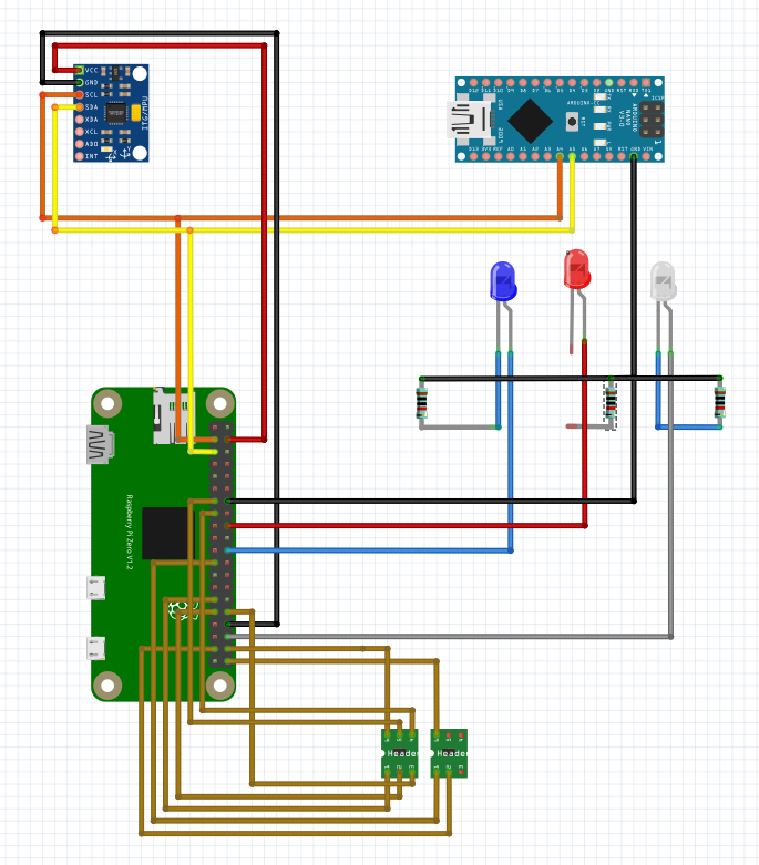
  1. MPU GY-80 communication using I2C protocol with I2C Device Addresses:

    1. I2C Address 0x1E is the HMC5883L

    2. I2C Address 0x53 is the ADXL345

    3. I2C Address 0x69 is the L3G4200D

    4. I2C Address 0x77 is the BMP085

  2. GPS UBlox connected to TX/RX directly.

  3. RC-In: using GPIO:  GPIO 5, 6, 12, 22, 27, 20, 21, 26.

  4. RC-out: using Arduino D11, D9, D3 & D10. where D9 is a motor output for Throttle. & D11 for Steering in the rover.

  5. For PCA9685 channels 1 & 3 are used and GPIO27 is used for enable the chip (not used in my code).

How to Start

First we need to compile ardupilot RZero branch. Using command: $ make rzero-rover

Then we can find the binary in subfolder ardupilot/build/rzero/bin/ardurover


We need to copy this file to Raspberry Pi Zero in /home/pi you can copy it in many ways, one of them is to open SDCard on your laptop and manually copy the file. Another easier way is to copy it using scp command.


scp ./build/rzero/bin/ardurover pi@YourRPI_IP:.


That is it.


When I run ardurover I choose it not to start until I connect to it using MissionPlanner or QGroundControl -my favorite- so that I can monitor each and every step.


sudo ./ardurover -A tcp:MyLapIP:wait -C:/ttyAMA0


You can also use other options such as:


sudo ./ardurover -A udp:MyLapIP:bcast -C:/ttyAMA0


Notice: If you make your mobile Wifi Hotspot  it will take IP 192.168.43.246 which so you can add this network to your RPI zero and make it connect to your QGC on your mobile phone.


You can choose to remove “wait” and ignore initializing GPS in your first tests.


AutoRun Service

Create a file at: /lib/systemd/system/ardurover.service


[Unit]

Description=My Sample Service

After=multi-user.target

[Service]

Type=forking

ExecStart=/home/pi/ardurover -A udp:192.168.1.100:10100:bcast -C udp:192.168.1.139:14550:bcast

Restart=on-failure

[Install]

WantedBy=multi-user.target


Important Notice:


In the above version I ran ardupilot on pure linux. But Ardupilot need RealTime OS so we need to update the Raspberry PI OS and add Real Time Features. 


To do that you need to follow steps from this link. It is straightforward yet not easy.


IMPORTANT real-time OS is not mandatory if you only run ardupilot without running extra apps. At least for rovers.

The Fatal Bug

This was totally unexpected. I found a bug that crashes ardupilot on RPIZero randomly. I was due to using RCInput_RPI class. I took me a while to figure it out but I could finally fix it in this
[AP_HAL_Linux: Fix RCInput_RPI Segmentation Fault #14842].

Conclusion

In this project I learnt how to define a board of in Ardupilot, adding and updating sensors. It also required decisions about design and wiring.

Useful Links


  1. Building an autopilot from scratch using Raspberry Pi Zero: Mini Zee.

  2. PXFmini.

  3. Code with PCA9685 enabled with segmentation fault fixed https://github.com/HefnySco/ardupilot/tree/ppr_RaspberryZ_PCA9685

  4. Code with Arduino MW-I2C enabled with segmentation fault fixed

https://github.com/HefnySco/ardupilot/tree/ppr_RaspberryZ


Sunday, October 1, 2017

Compiling WebRTC on Ubuntu

In this topic I want to share an experience in details. Maybe it helps someone trying to compile WebRTC. If you do not know aht is WebRTC then this topic is definitely not interested for you.

Compiling WebRTC is a nightmare experience that you do not need to go through in order to use WebRTC in your application. But some rare times you have to and this where this topic becomes vital.


The following steps are for compiling WebRTC branch 50 on Ubuntu 16.04.


1- Preparing Environment:


     1.1 Goto page: https://cs.chromium.org/chromium/src/build/install-build-deps.sh and download script from it named install-build-deps.sh you cannot use wget, you need to open the page and copy the script into a file.
     1.2 Run this script that will install all prerequisites needed for compiling process.
    $ ./build/install-build-deps.sh  --no-chromeos-fonts 


2-   Install Depot Tools

     1.1 Download depot_tools
     
$ git clone --depth 1 https://chromium.googlesource.com/chromium/tools/depot_tools.git
     
     1.2 now add path of depot tools to $PATH by running the following command  
      
$ export PATH=`pwd`/depot_tools:"$PATH"


3- Download & Compile WebRTC


 1.1 Download Source Code 

this steps takes looooong time to download source code, without a good Internet connection you have no hope in completing this. I myself decided to get a VPS on net with extra 50GB HD for about $10 per month to be able to compile this code. 

$ mkdir webrtc-checkout

$ cd webrtc-checkout

$ gclient config https://chromium.googlesource.com/external/webrtc.git@branch-heads/50 --name=src

$ gclient sync --force --with_branch_heads 

$ gclient sync --force --with_branch_heads --nohooks 


1.2 Define Building Parameters


$ export GYP_DEFINES="target_arch=x64 host_arch=x64 build_with_chromium=0 use_openssl=0 use_gtk=0 use_x11=0 include_examples=0 include_tests=1 fastbuild=1 remove_webcore_debug_symbols=1 include_pulse_audio=0 include_internal_video_render=0 clang=1 "

given you are in ./webrtc-checkout

$ cd src

$ git checkout branch-heads/50

1.3 Generate Build Script 

$ gclient runhooks 

1.4 Compile Code

after running above commands you can find two folders ./webrtc-checkout/src/out/Release and  ./webrtc-checkout/src/out/Debug contain build scripts for building WebRTC based on the GYP_DEFINES that you chose above.

$ ninja -C ./out/Release 
or
$ninja -C ./out/Debug 

You will wait for a 2923 files to be compiled. On that small machine I used it took around 30 min to compile.


1.5 Generate Headers & Libraries


Now you finally have WebRTC compiled. Assuming you chose to compile Release the you will find  binaries in /src/out/Release

Now you need to archive all .o objects into libwebrtc_full.a  and you need to have .h headers in a directory.

to generate libwebrtc_full.a in a folder lib assuming you are still in ./webrtc-checkout/src


$ mkdir ../lib/

$ find  ./ -name "*.o" -and -not -name do_not_use -and -not -name protoc -and -not -name genperf -exec ar crs ../lib/libwebrtc_full.a {} +

$ mkdir ../include


$ find ./ -name *.h -exec cp --parents '{}' ../include ';'


Please Check GitHUB for more details on sources & samples covering this topic 


For higher branch numbers such as 58, 60 ...etc. you need to replace step "1.3 Generate Build Scripts" commands with:


$ gn clean out/Release 

$ rm -rf ./out

$ gn gen out/Release


Problems does not end here... but above steps should work straight forward .


Tuesday, September 15, 2015

Linux Experience

This Year I was very busy with developing Andruav.com an RC related android application. This September  2015 I finish 1 year working on it. It is a sophisticated app to develop, however I hope it is alot easier to be used.

I have been a Windows developer for more than +15 years, a C++ anti-java person. Well I regret that, I do love windows, however Java is a very nice language, especially when it comes to Android. Also Linux is an excellent platform that I was away from. Now my Laptop is Ubuntu :)

Anyway when I was looking for an inexpensive server for Andruav.com I had to go to Linux, at first I thought buying a VPS Ubuntu means a remote desktop with GUI, but I found my self lonely in front of back screen and all I have is ssh to connect :(.  That was horrible at the beginning, but later I was very comfort with it. I had to go through alot of issues that I will summaries here for other people who want to use Linux easily.


The platform I use is Ubuntu 12.04


Steps of installing LAMP on Ubuntu 14.04


1. Install Apache

sudo apt-get install apache2

2. Install MySQL

sudo apt-get install mysql-server
* reconfig
/usr/sbin/dpkg-reconfigure: mysql-server-5.5

3. Install PHP

sudo apt-get install php5 libapache2-mod-php5

4. Restart Server

sudo /etc/init.d/apache2 restart

5. Check Apache

http://localhost/.


7. Installing MySQLAdmin

apt-get install php5-mysql http://www.thetechrepo.com/main-articles/488.html
sudo apt-get install phpmyadmin

*reconfig phpmyadmin database:
sudo dpkg-reconfigure phpmyadmin

Add extension=mysqli.so (near other 'extension=' lines) line to your php.ini


8. Restart Server

sudo /etc/init.d/apache2 restart


If you execute these commands in order you will have LAMP on your Ubuntu


A Python Experiment in Gyro Calibration & Drift Cancelling


This article is to share my findings in gyro calibration. I tried to make a python script that uses data comes from mobile phone [S5 that has 6050 IMU]. It was a good chance to write simple code and visualize results much easier than doing so on Arduino with IMU 6050 attached. But still the concept is the same.
I used this mobile app, this is not the only one, so you can choose other if you want.

I used three approaches for Gyro calibration.
First Approach:
This is the normal approach where you read values from Gyro and then divide total by number of reads. This is the average value. Almost all quadcopter firmwares do this step before arming to make sure that the value that is read from gyro represents zero rad/s i.e. no rotations.
gyro from value will be:
     Gyro = (gyro_raw - gyro_avg ) * timediff
      where gyro_avg is the average measured by reading a sample values and divide over count.
There is nothing wrong in above approach, it is simple, and really can make your quad flies. 
Second Approach:
The second approach was almost the same, but in this trial, I took values from First averaging algorithm as a first guess,  then I ran an inner loop that tries to get error based on the original average, and tries to add correction to it.
gyro of value will be:
      Gyro = (gyro_raw - gyro_avg_dyn) * timediff
      where gyro_avg_dyn: is the best average with least error.
I find this is a equivalent of running the first approach method multiple time and try to get the best average with least error. It could be smarter than blindly get an average after n counts -first method- where you can test some values in between. This also may be more useful when using integers rather than decimal in 8-bit chips.
Third Approach:
This approach was a bit different. It assumes that original average will give zero error for the noise, however drift will still occur, and it is in one direction. So if you integrate values from gyro it will keep either increasing or decreasing in one direction -as an overall behaviour-. 
The idea was to try to read the rate of which drift occurs and store it in a value called Gyro_AvrDriftRate. The unit of this value will be rad/sec^2.
So the Value of Gyro will be:    

      Gyro = (gyro_raw - gyro_avg - (gyro_avgdriftrate * timediff) ) * timediff
     
       where gyro_avg is the average measured by reading a sample values and divide over count.
      and gyro_avgdriftrate is drift rate per second

Drift already affects the original average value, as gyro_raw is not random values with normal distribution around an offset value; as it has drift component inside. and so the original average has a skew from the zero offset. In the third approach the drift will appear clearly in the integration of readings and using time-difference one can estimate a rate for the drift.

Actual Results:

Script Logic:
     1- calculate average and drift using the three methods.

    
 2- while loop:
              a. read gyro_raw
              b. calculate gyro_value_method1,2,3

              c. integrate these values into three different variables gyro_x1_int, gyro_x3_int, gyro_x3_int

              d. print result
The best approach should have the least absolute value i.e. the nearest to zero.

Results:

I ran the code several times, the result is not the same every time. but in general the third method is promising, as in
many cases it gives less drift than the other methods.

the third method is the one has x_rad/s2 label.
Also the second method sometimes get stuck in local minimum, as it reads less values in the inner loop, and sometimes get worst that normal average. 
This is not always the case. Anyway I hope this could be a small start for others to make much more investigation.

Note: sometimes values sent from mobile jumps in crazy way without movements, so I just added a skip statement to skip those values, and I assume you run this script while leaving your mobile with no movement at all.
imu_gyroCalibration.py

Latest Code version is available at this link

Thursday, August 7, 2014

ZERO_PID Tunes for Multirotors Part#2

Introduction


                From more than a month from now Aug 2014, I posted a blog titled ZERO_PID Tune for Multicopter and also here on my blog, It was about an algorithm I developed that allows quadcopter pilot to reset Gyro PIDs to ZERO, and fly! Using this algorithm, the quadcopter was able to generate valid values for P & I, and can successfully fly, the demo was on Multiwii code. Since then I was working on enhancing this algorithm, as I discovered some opportunities for improvment.
 Multiwii_GTune1.0.2.zip

First Version Issues

                 Although as you can see in the video that quadcopter really flies, there was a devil in the details. P-factor & I-factor would saturate if you fly long enough – I discovered this later few days after the video-. Although quadcopter was safely taking off, but flying for a long time -1 to 2 min- in this mode will make P & I saturate especially if you play with sticks hard.
Another issue I have discovered in the first version was calculating I-factor assuming it is a percentage of P-factor. Although it was calculated separately from P-factor, it ended up as a percentage of P-factor.

ZERO_PID Model


       Although my background is engineering, but I am not a big fan of mathJ, so I started to simplify the problem as much as possible, and avoid complex math. The model depends on angular velocity of gyros only. It assumes there is no interference between different axes –which is true theoretically at least- as actual Gyro MEMS has slight interactions between axes.

       First, let us start by a quad arm with a motor on it as in the figure, initially the motor is running, but you do not know if it is running fast enough to generate exact thrust to keep the arm with angular velocity zero. Again let’s assume that the motor is not producing enough thrust, so when reading the gyro we will get V1 = v1. With single value you cannot judge, you need to read two values, so you wait until the next IMU loop and read V2=v2.
       Now assume that both V1 & V2 have the same signs. This means the same direction, which is falling down –counter clockwise in the figure-.
Condition#1:     If V2 > V1 : this means the arm is accelerating and the quad in danger of flip. So let us reduce the P value by one if the difference is high enough.
Condition#2:     If V2 < V1 : this means the arm is decelerating and the quad is trying to adjust itself to reach angular velocity zero. However there is a danger here that the deceleration is so fast so that it will not only stop the arm but will move in the other direction and start oscillations. So let’s decrease P value by one if the difference is high enough.
Please note that by design, quad stability is active stability, i.e. you need to monitor and adjust to keep it stable, so whatever the P value is, it will oscillate, the idea here is the oscillation amplitude should be minimal.
Condition#3: What if V1 & V2 has different signs, i.e. our quad arm has reversed its rotation direction. This case is ignored as it will always happen due to oscillations as I mentioned in the previous paragraph. And we rely on condition 2 to minimize oscillations.   
What if the arm –in the figure- rotation direction is clockwise, in this case we are calculating the right arm that is falling down. That is why we use abs(Error) . So we always consider the falling arm.
ZERO_PID algorithm can be written now as follows:
void G_Tune (Error)  {
                If (Sign(Error) == Sign (OldError))
               {
                       If ((abs(Error) - abs (OldError)) > High_Enough _1) // we are falling down.
                      {
                           P = P + 1;
                      }
                      If ((abs(Error) - abs (OldError)) <  - High_Enough_2 ) // we may oscillate.
                     {
                         P = P - 1;
                     }
                }
               OldError = Error;
}

Simple :) and yet it works. Well almost :)
As we can see the above algorithm changes P-factor only. In the first version I used a parallel condition for I-factor that increases and decreases it with 0.1 steps. Later I discovered this was not the best approach.

Challenges
Algorithm idea looks simple; however we need to consider some points that affect the performance of the algorithm.
      1. Aerodynamic Factor:  The above algorithm updates OldError = Error, actually it is not reasonable to assume that applying the updated P factor once in the PID and read the very next value will reflect the instant correct response, we need to consider motor acceleration and deceleration, as well as frame/propellers inertia, a lot of factor that makes our assumption not solid enough. In the first version I tried to use complementary filter, and give a large weight for the new value, however keeping the old values so that we can have idea of the average performance. However we still read the very next action and update P-factor after one read. In the latest version I have defined time_skip parameter that make sure that the algorithm is executed one time each ntimes of PID calls. See the figure, the curve are the values from gyro while the bar chart shows samples taken by the algorithm. In practice I found time_skip  from 7 to 20 i.e. 14ms to ms gives the correct response, out of this range the quad still flies but the model assumption is not valid and it either saturate or stay in Zero. For low value of time_skip it stays in zero because V2 – V1 is small and within a safe range so quad assumes that this is a normal speed. Also V2 in this case does not represent the effect of previous updated P. also when time_skip is high, quad reads random values with large difference, and in this case condition #1 wins and P saturates, also still this is a fake reading. So time_skip is a critical parameter, which works well as long as we are in this range 7 – 20.


      2. Taking-Off & Landing: When you land with your quadcopter, once the quad hit the ground –even smoothly-, you will be able to see sudden peeks on the accelerometer graph. It is more clear on the Acc-Z, and this means calculated P could be corrupted during take-off or landing especially. Handling this was relatively easy. I just added a condition not to calculate P when Thrust is less than one third throttle. So now you can land and then switch from G_Tune to ACRO mode, you don’t need to do that in the air, however you can still do it safely as in the first version.

         
      3. What is Error Input Parameter: PID takes Error as an input, error could be gyro reading as in hefnycopter firmware , or as in multiwii it is the difference between stick value and correspondent gyro, i.e. between aileron value and the x-axes gyro. In the first version as used the same Error value as in multiwii, but this was not very good, as it means that when you make sudden stick change it will give error and the algorithm will correct P accordingly, although the current P value could be enough and correct. First I tried to define high and low boundaries for Error values, but after more thinking I was convinced that we need to consider only gyro reading as an input, and leave stick for multiwii algorithm.

         
      4. Condition #2: Please re-read that condition again “However there is a danger here that the deceleration is so fast so that it will not only stop the arm” there is a vague word “danger”. Well how can we know if the deceleration is healthy and arm is slowing down in a proper speed, or it is slowing down too fast, well I don’t J. I tried some ranges and I found thatHigh_Enough _2 should be 1.5 to 2 times larger than High_Enough _1. Lower value for High_Enough_2 will make P always ZERO which is logic. And high value of it will make P saturate as condition #2 is hardly achieved because of the large barrier value.


Calculating I-Factor

              
                As I mentioned in the beginning of this article, I was calculating I as a percentage of P. Well in an article about sensors & PIDs I mentioned that I component in PID for gyro is used for restoring, it acts as a memory, because it is based on many values not the most recent one as P or the difference as D. I think about I component as the DC current in a signal or as a trim in your TX. Try to fly in Acro mode with I factor equal to Zero, you will find that if you tilt your try then take your hand of the sticks it will not get back, if you add some values to I-factor, it will tend to restore itself. And this is obvious because the I-component –i.e. the integration value not the I factor value- that was accumulated to overcome your stick need to be reduced back to zero. To have this effect I used a simple average variable to calculate the average value of gyro readings in a time window, and if the value is not Zero –higher or lower than a certain range- I is incremented otherwise it is decremented.

A Workable Code


                I attached a working code, you can use it to fly in ACRO mode only, as I used other PID parameters to as ZERO_PIDs parameters in order to study the effects above.

                LEVEL_P: represents High_Enough _1
                LEVEL _I: represents High_Enough_2
                ALT_P: represents time_skip counts.
                ALT_I: represents number of samples used for averaging Error for calculating I factor.
Note: if you put value ALT_I = 0.01 this means actually 10, as the minimum value is 0.001 which is 1. Same for other values, for example LEVEL_P = 1.0 means 10 and value 0.1 means 1 as there is no 0.001 and this is the minimum value for P, so take care when you play with values.

My Samples

              These figures are taken from MultiWii EZ-GUI for 3 flights:

                 as we can see High_Enough_1 = 10 & High_Enough_2 = 15 works very nice. time_skip here is 10 and values that are read for averaging to calculate I-factor is 100.
                 as I increased High_Enough_2 to 20 P values started to raise, especially in the third trial where I played more aggressive with quad compared to the calm first two flights.


Final Notice
                Still everything is experimental, and try it on your OWN RISK, try to fly smoothly and dont take off suddenly, let it leave ground easy.
 Latest Code is Here